



Introduction
The P0887 diagnostic trouble code (DTC) – defined as “TCM Power Control Circuit High” – is a common issue affecting the 9-speed ZF transmission control modules (TCMs) found in Jeep Cherokees and other FCA vehicles. This article provides a detailed, step-by-step guide on repairing this fault by replacing the corrupted software with known-good firmware from a functioning TCM.
Unlike hardware failures, this issue is software-related, making it recoverable through proper reading, writing, and programming techniques.
Understanding the Problem
The Fault Code: P0887
- DTC Name: TCM Power Control Circuit High
- Affected Component: ZF 9-speed automatic transmission TCM
- Vehicle: Jeep Cherokee (and other models using the ZF 9HP transmission)
- Root Cause: Software corruption within the TCM’s internal memory
Why Software Replacement Works
The TCM contains two critical memory regions:
- Internal Flash – main operating firmware
- Internal EEPROM – vehicle-specific calibration data, adaptation values, and configuration
When software corruption occurs, reprogramming the TCM with a known-good firmware image from a working module can restore normal operation without replacing the entire unit.
Tools Required
| Item | Purpose |
|---|---|
| Xhorse Multi-Prog programmer (or compatible) | Reading/writing TCM firmware |
| Soldering iron | Removing plastic cover sections and soldering boot point connections |
| Thin wires | Connecting to boot points P1 and P2 |
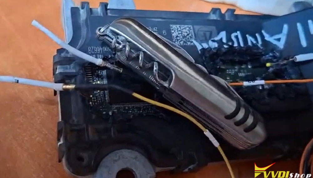
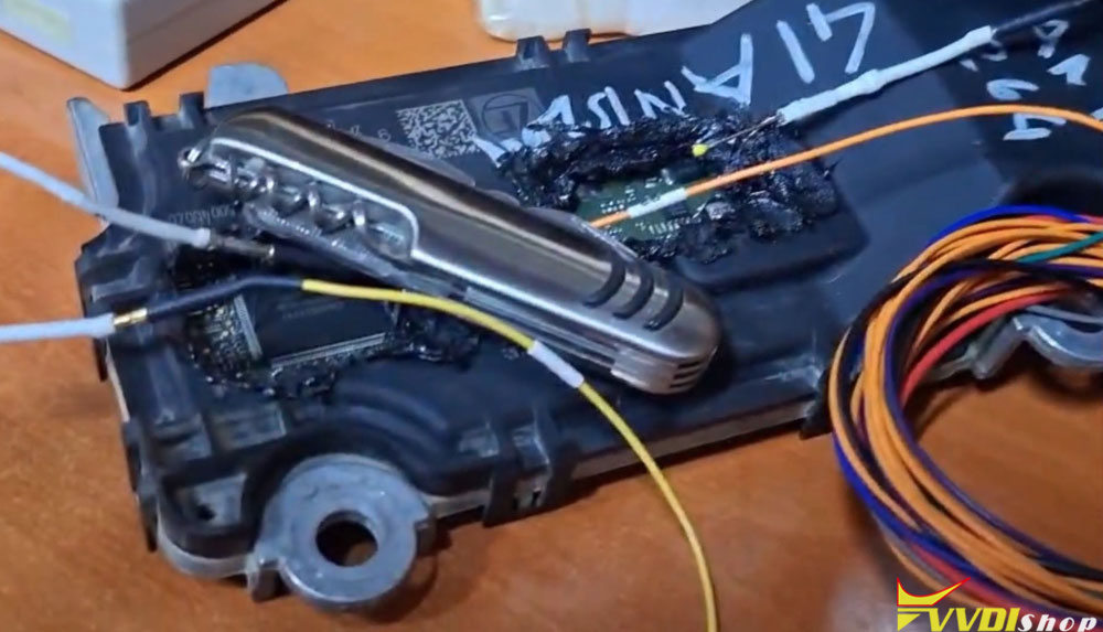
| Needle / probe | Connecting to boot point P3 (soldering is not practical here) |
| Pocket knife or weight | Holding the needle in place under pressure |
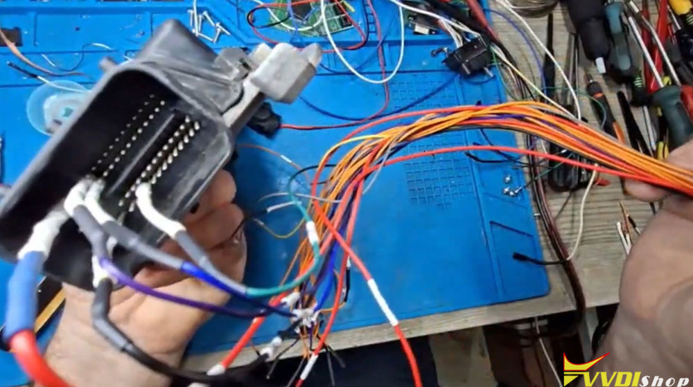
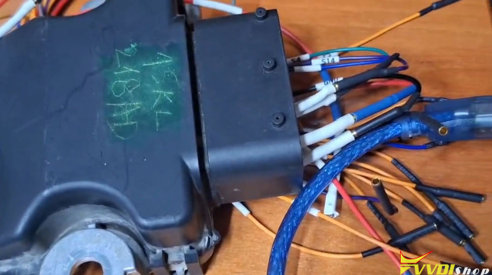
| Adapter harness | Connecting to the TCM front terminals |
| Black silicone or heat source | Resealing the cover after repair |
Step 1: Accessing the TCM and Identifying Boot Points
Cover Modification – Not Full Removal
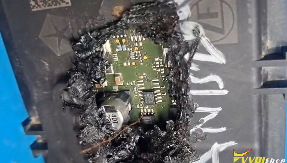
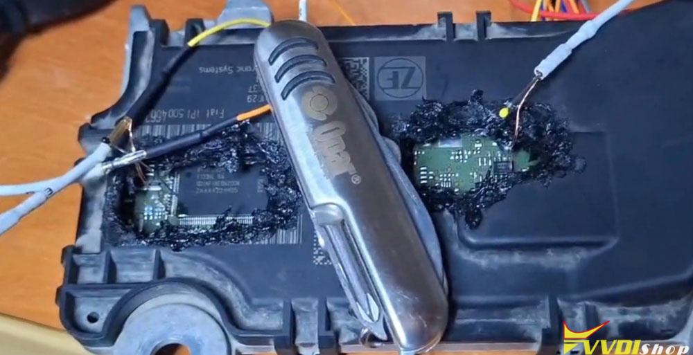
The TCM cover is difficult to remove entirely without risking damage to the pins and terminals. For this reason, the preferred approach is to cut two specific areas on the cover to access the boot points underneath.
- First area – Use a soldering iron to melt and remove plastic from the designated location.
- Second area – Repeat the process carefully.
Important: Proceed with caution. Going too deep can damage internal components.
Boot Points Overview
Under the cover, there are three boot points:
- P1 – accessible on the PCB
- P2 – accessible on the PCB
- P3 – located in a difficult-to-solder position
These boot points are required to put the TCM into programming mode for reading and writing.
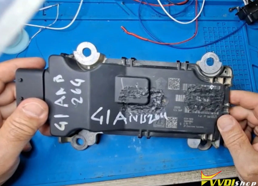
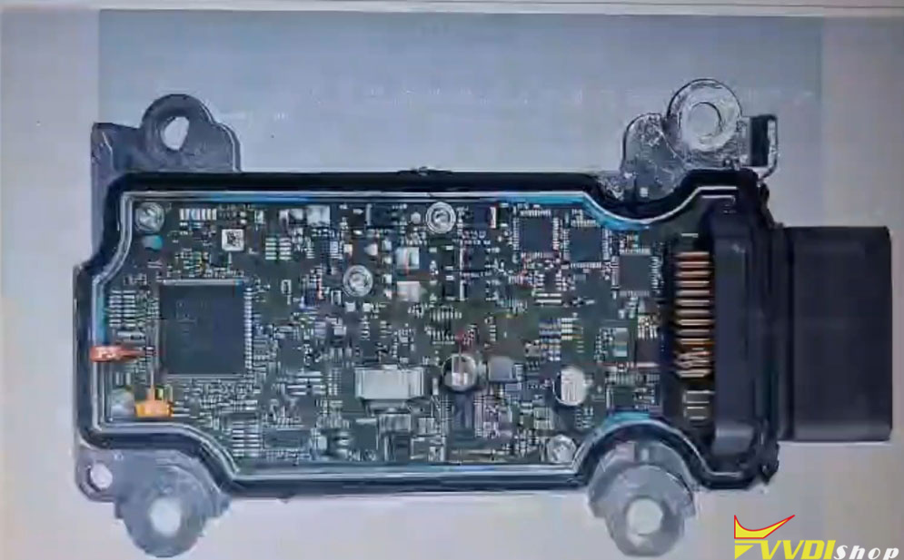

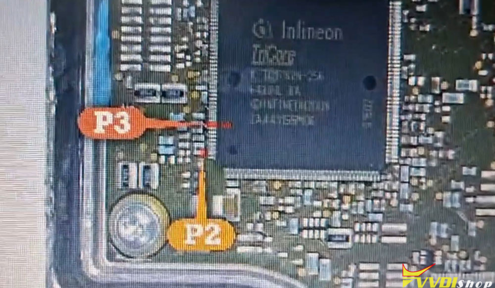
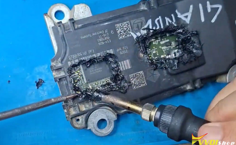
Step 2: Making the Connections
Pinout Reference
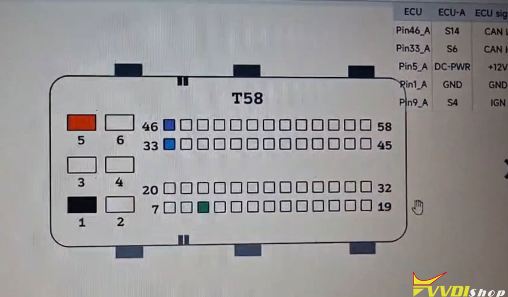
The TCM connector provides the following essential connections:
-
Power – module supply voltage
-
Ground – module ground
-
CAN High – communication line
-
CAN Low – communication line
-
Run/Start – ignition/start signal
Boot Point Connections
Using the Multi-Proc adapter and schematic:
| Boot Point | Connection Method |
|---|---|
| P1 | Soldered thin wire |
| P2 | Soldered thin wire |
| P3 | Needle/probe held under pressure (soldering is impractical) |
For P3, a pocket knife or weight is used to maintain steady pressure on the needle against the contact point.
Wiring diagram
The connection layout follows this pattern:
-
Adapter connects to front terminals
-
P1, P2, and P3 wires/probes are routed to the Multi-Proc programmer according to the pinout schematic.
Step 3: Reading the Faulty TCM Software
Software Setup
Launch the Multi-Prog software.
Select Jeep Cherokee.
Choose ZF 9-speed transmission control module.
Reading Process
Connect to the module – the software confirms successful ECU connection.
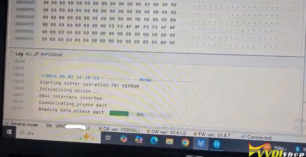
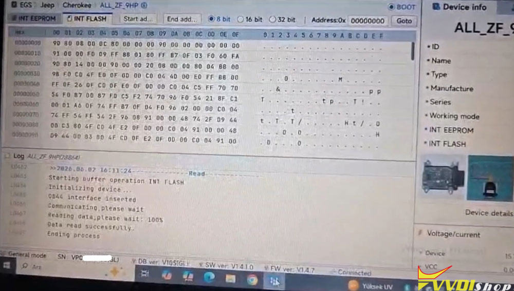
Read Internal EEPROM – saves the EEPROM data from the faulty TCM.
Read Internal Flash – saves the main firmware from the faulty TCM.
Note: Even though the module is faulty, it’s good practice to back up its data before making changes. This allows for recovery in case of errors.
Saving the Files
Save the following files with clear names:
- Faulty TCM – EEPROM file
- Faulty TCM – Flash file
Step 4: Reading the Good Working TCM Software
Disconnect the faulty TCM and connect the known-good working TCM using the same wiring and boot point setup.
Repeat the reading process:
Read Internal Flash
Read Internal EEPROM
Save these files as the source software for the repair.
The good working TCM uses the same hardware but has uncorrupted software. Its flash and EEPROM images will replace the faulty data.
Step 5: Writing the Good Software to the Faulty TCM
Preparation
Reconnect the faulty TCM to the multi prog programmer.
Confirm successful ECU connection.
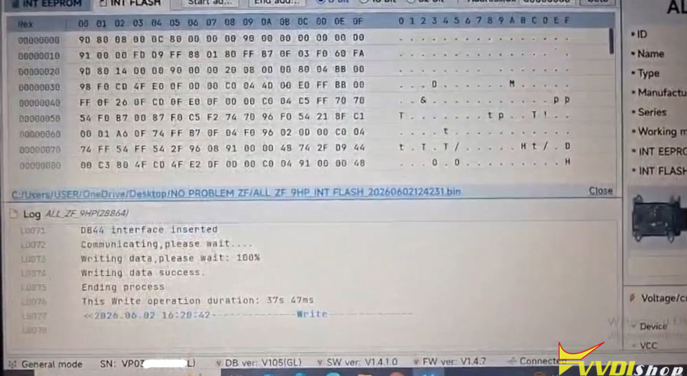
Writing Procedure
Open the good working module’s EEPROM file.
- Write EEPROM – operation successful.
- Open the good working module’s Flash file.
- Write Flash – operation successful.
Why write both? While writing only the flash might be sufficient, writing both ensures complete data integrity and avoids potential mismatches. The technician in this guide chose not to risk it.
Step 6: Verification and Final Assembly
Post-Programming Checks
Carefully remove all soldered wires.
Inspect the PCB to ensure there are no shorts between adjacent legs or pads.
Clean the soldered areas thoroughly.
Resealing the Cover
After confirming the repair:
- Option A: Apply black silicone around the cover edges to seal it.
- Option B: Heat the plastic sections again to soften and press them back into place.
The technician in this guide used the heat method, melting the plastic to re-form the cover sections.
Summary Table
| Step | Action | Details |
|---|---|---|
| 1 | Access boot points | Cut two cover areas, locate P1, P2, P3 |
| 2 | Connect hardware | Solder P1 & P2, use needle for P3 |
| 3 | Read faulty TCM | Back up EEPROM + Flash |
| 4 | Read good TCM | Source files for repair |
| 5 | Write good software to faulty TCM | Write EEPROM first, then Flash |
| 6 | Verify & reassemble | Check for shorts, seal cover |
Conclusion
The P0887 fault code on ZF 9-speed TCMs is a software-related issue that can be resolved without replacing the entire transmission control module. By carefully accessing the three boot points, reading a known-good TCM, and writing its firmware to the faulty unit, normal operation can be restored.
This procedure requires patience, precision, and steady hands, but it is a cost-effective alternative to module replacement. Always double-check connections, avoid short circuits, and verify the data before reassembly.