


Traditionally, when working with newer Porsche immobilizer systems, technicians need to remove the BCM (Body Control Module) and read CPU data directly. Using tools like Xhorse VVDI PROG to extract Porsche BCM data (2M25J/5M48H/ 1N35H) requires not only component removal but also cutting a wire near the crystal oscillator.
Risks of Wire-Cutting:
- PCB Damage: Excessive force during cutting may scratch the lower-layer circuit board, permanently damaging the BCM.
- Poor Solder Recovery: Many technicians lack soldering expertise, leading to:
- Short Circuits: Improper wire reconnection causes grounding issues.
- BCM Failure Symptoms: Relays in the BCM may flicker continuously, and the vehicle becomes unresponsive.
- High Failure Rate: Less experienced technicians face significantly higher risks.
Solution:
To minimize risks, an alternative method is proposed.
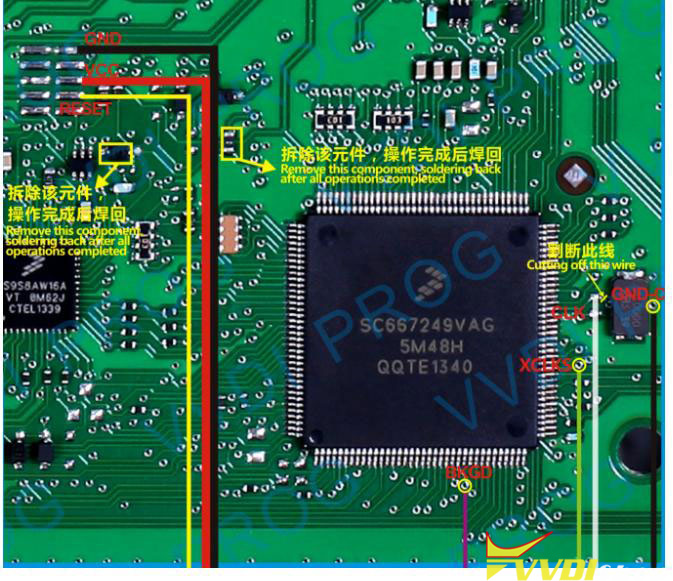
Component Removal Instructions for Porsche BCM (Body Control Module)
Front-Side Component Removal:
The following components on the front side of the PCB must be removed:
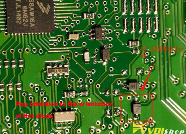
- Diode
Critical Note: Orientation must be correctly identified and maintained. Incorrect placement will cause failure.
- 0-ohm resistor
- Crystal oscillator
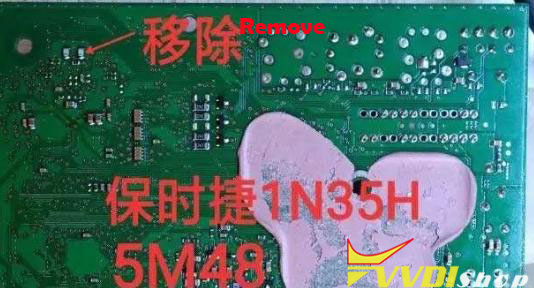
Back-Side Capacitor Removal:
After front-side removal, capacitors on the PCB’s back side must also be detached.
Location varies by CPU model:
2M25J
1N35H
5M48H
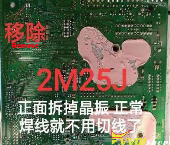
This way we don’t need to cut the wires.
Xhorse also has Porsche BCM solder free adapter which is safer than two soldering method.